
This article aims to help readers understand how to use the 8086/8088 processors by explaining their instruction formats, addressing modes, and instruction sets. It also covers important assembler directives and operators used in assembly language programming for these processors. While various assemblers exist for programming with 8086/8088, this article focuses on those compatible with MASM (Microsoft MACRO ASSEMBLER), which have similar syntax and principles.
MACHINE LANGUAGE INSTRUCTION FORMATS
A machine language instruction format comprises multiple fields, each serving a specific purpose. The primary field is the operation code (opcode), which specifies the type of operation the CPU should perform. Additionally, the instruction format includes operand fields, which provide further information necessary for the CPU to execute the instruction effectively. The CPU utilizes the data stored in these fields to carry out the instruction.
There are six general formats of instructions in the 8086 instruction set. The length of an instruction may vary from one byte to six bytes. The instruction formats are described as follows:
One-byte Instruction Format: This format is the shortest, consisting of only one byte. In some cases, the instruction may imply its operands without explicitly specifying them. If the instruction involves a register operand, the least significant 3 bits of the opcode are used to denote the register. However, if the instruction does not involve a register operand, the entire 8 bits form the opcode, and the operands are implicitly understood based on the instruction’s context. This format is typically used for simple and frequently executed operations that require minimal additional data.
Register to Register Instruction Format: This format spans two bytes in length. The first byte contains the opcode along with a bit (typically denoted as ‘w’) indicating the width or size of the operand. The second byte of the instruction code indicates the register operands and the R/M (Register/Memory) field, which specifies whether the operands are registers or memory addresses. This format is commonly used for instructions that involve operations between two registers, allowing for efficient data manipulation within the CPU registers.
The register represented by the REG field is one of the operands. The R/M field specifies another register or memory location, i.e. the other operand.
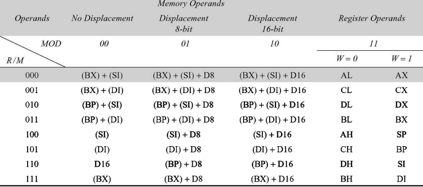
Register to/from Memory with no Displacement Instruction Format: This format shares the same length as the register to register format, spanning two bytes. However, it differs in the inclusion of the MOD (Mode) field, which determines the addressing mode used. The MOD field, along with the R/M (Register/Memory), REG (Register), and W fields, are determined based on values specified in Table 2.2. The MOD field indicates the mode of addressing, dictating how the CPU accesses memory or registers to perform the instruction. This format is commonly utilized for instructions involving data transfer between registers and memory locations without any displacement.
Register to/from Memory with Displacement Instruction Format: This format extends the register to/from memory without displacement by incorporating one or two extra bytes specifically for displacement. Despite this addition, the overall format remains consistent with the 2-byte structure of the register to/from memory without displacement format. This allows for efficient handling of memory operations where a fixed offset or displacement is necessary for accessing memory locations. The inclusion of displacement facilitates more flexible memory addressing, enabling instructions to work with data stored at specific memory addresses.
Immediate Operand to Register Instruction Format: In this format, both the first byte and the 3 bits from the second byte, which typically represent the REG field in the register to register format, are utilized for encoding the opcode. Additionally, this format includes one or two bytes dedicated to immediate data. The complete instruction format is structured as follows. This format is commonly employed when an immediate value needs to be loaded directly into a register for immediate use in an operation.
Immediate Operand to Memory with 16-bit Displacement Instruction Format: This instruction format necessitates 5 or 6 bytes for encoding. The initial 2 bytes encompass crucial information pertaining to the opcode, MOD (Mode), and R/M (Register/Memory) fields. The subsequent 4 bytes consist of 2 bytes allocated for displacement and an additional 2 bytes designated for data storage. This format facilitates the direct loading of immediate data into a memory location with a 16-bit displacement offset. It is often utilized when immediate values need to be stored directly in memory for subsequent retrieval or manipulation.
The opcode typically resides in the first byte of an instruction, but in some cases, a register destination occupies the first byte, while in a few others, the 3-bit opcode may be in the second byte. The opcodes include single-bit indicators with specific definitions and significances:
- W-bit: Indicates whether the instruction operates on 8-bit or 16-bit data/operands. W = 0 signifies 8-bit operands, whereas W = 1 denotes 16-bit operands.
- D-bit: Applicable for double operand instructions. If D = 0, the register specified by the REG field is the source operand, else it’s the destination operand.
- S-bit: The sign extension bit, used alongside W-bit to specify the operation type. For instance, S = 0, W = 0 indicates 8-bit operation with an 8-bit immediate operand.
- V-bit: Used in shift and rotate instructions. V = 0 when the shift count is 1 and V = 1 when CL contains the shift count.
- Z-bit: Employed by REP instruction for loop control. Z = 1 executes the instruction with REP prefix until the zero flag matches the Z bit.
The REG codes for different registers (as source or destination operands) are assigned binary codes. Segment registers, being four in number, require 2 binary bits for coding, whereas other registers, being eight in number, need at least 3 bits. Additionally, 16-bit registers can be coded using the W bit.
Note that DS is the default data segment register for operand referencing. CS serves as the default code segment register for storing program codes, while SS is for stack data accesses, and ES for destination data storage. Addressing modes in 8086 instructions depend on operands, suggesting how the effective address may be computed for locating the operand, if in memory.
ADDRESSING MODES OF 8086
Addressing modes refer to methods of locating data or operands within a computer’s memory. Depending on the types of data used in an instruction and the memory addressing modes employed, an instruction may belong to one or more addressing modes, or none at all. Addressing modes describe the operand types and the manner in which they are accessed during instruction execution.
Instructions can be categorized based on the flow of instruction execution into two main types:
- Sequential Control Flow Instructions: These instructions, upon execution, transfer control to the next instruction appearing immediately after them in the program sequence. Examples include arithmetic, logical, data transfer, and processor control instructions. They facilitate the sequential execution of program code.
- Control Transfer Instructions: In contrast, control transfer instructions redirect program flow to a predefined address or an address specified within the instruction itself upon execution. Examples of control transfer instructions include INT (interrupt), CALL (subroutine call), RET (return from subroutine), and various jump (JMP) instructions. They enable branching and looping within program code by directing execution to different parts of the program based on specified conditions or addresses.
The addressing modes for sequential and control transfer instructions are explained as follows:
- Immediate Addressing: Immediate data is directly included in the instruction, appearing as successive bytes. Immediate data can be either 8-bit or 16-bit in size. It’s commonly used for providing constants or immediate values directly to instructions for immediate computation.
- Example 1:
MOV AX, 0005H(loads the immediate value 0005H into the AX register) - Example 2:
MOV BL, 06H(loads the immediate value 06H into the BL register)
- Direct Addressing: In direct addressing mode, a 16-bit memory address (offset) or an I/O address is explicitly specified within the instruction. This mode directly accesses a memory location or an I/O port.
- Example 1:
MOV AX, [5000H](loads the value stored at memory address 5000H into the AX register) - Example 2:
IN AL, 80H(reads a byte from I/O port 80H into the AL register)
- Register Addressing: Data is stored in a register and referenced using that particular register. All registers, except IP (Instruction Pointer), may be used in this mode. It’s frequently used for efficient manipulation of data stored in registers.
- Example 1:
MOV BX, AX(copies the contents of the AX register into the BX register) - Example 2:
ADC AL, BL(adds the contents of the BL register to the AL register with carry)
- Register Indirect Addressing: The memory location’s address containing data is indirectly determined using offset registers such as BX, SI, or DI. The default segment is either DS (Data Segment) or ES (Extra Segment). This mode is often used for accessing data structures or arrays.
- Example:
MOV AX, [BX](loads the value stored at the memory address pointed to by the BX register into the AX register)
- Indexed Addressing: The offset of the operand is stored in one of the index registers (SI or DI). DS serves as the default segment for index registers SI and DI. This mode is useful for accessing elements of arrays or data structures.
- Example 1:
MOV AX, [SI](loads the value stored at the memory address pointed to by the SI register into the AX register) - Example 2:
MOV CX, [DI](loads the value stored at the memory address pointed to by the DI register into the CX register)
- Register Relative Addressing: Data is available at an effective address formed by adding an 8-bit or 16-bit displacement with the content of any one of the registers (BX, BP, SI, or DI) in the default segment. This mode is useful for accessing data structures with variable offsets.
- Example 1:
MOV AX, 5000H[BX](loads the value stored at the memory address DS:5000H + BX into the AX register) - Example 2:
MOV 10H[SI], DX(stores the value in the DX register at the memory address DS:SI + 10H)
- Based Indexed Addressing: The effective address of data is formed by adding the content of a base register (BX or BP) to the content of an index register (SI or DI). The default segment register may be ES or DS. This mode is commonly used in array processing.
- Example 1:
MOV AX, [BX][SI](loads the value stored at the memory address DS:[BX] + SI into the AX register) - Example 2:
MOV [BX][DI], AX(stores the value in the AX register at the memory address DS:[BX] + DI)
- Relative Based Indexed Addressing: The effective address is formed by adding an 8 or 16-bit displacement with the sum of contents of any one of the base registers (BX or BP) and any one of the index registers (SI or DI), in a default segment. This mode allows for flexible addressing of data structures.
- Example 1:
MOV AX, 50H[BX][SI](loads the value stored at the memory address DS:BX + SI + 50H into the AX register) - Example 2:
ADD 50H[BX][SI], BP(adds the value in the BP register to the memory location DS:BX + SI + 50H)
For control transfer instructions, addressing modes depend on whether the destination location is within the same segment or in a different one. They can be categorized into intersegment and intrasegment addressing modes. Intrasegment modes deal with control transfers within the same segment, while intersegment modes involve transfers between different segments. Each mode has its own variations based on the method of addressing.
INSTRUCTION SET OF 8086/8088
The 8086/8088 instructions are categorized into the following main types, each serving specific functions elucidated with examples where applicable:
- Data Copy/Transfer Instructions: These instructions are employed to transfer data from a source operand to a destination operand. Operations include store, move, load, exchange, input, and output instructions.
- Arithmetic and Logical Instructions: Instructions performing arithmetic, logical, increment, decrement, compare, and scan operations fall under this category.
- Branch Instructions: This category comprises instructions transferring control of execution to a specified address. Included are call, jump, interrupt, and return instructions.
- Loop Instructions: Instructions prefixed with REP and utilizing CX as a count register can implement unconditional and conditional loops. LOOP, LOOPNZ, and LOOPZ instructions are part of this category, useful for implementing various loop structures.
- Machine Control Instructions: These instructions regulate the machine’s status. NOP, HLT, WAIT, and LOCK instructions fall under this class.
- Flag Manipulation Instructions: Instructions directly impacting the flag register belong to this group. Examples include CLD, STD, CLISTI, etc.
- Shift and Rotate Instructions: This category encompasses instructions involving bitwise shifting or rotation in either direction, with or without a count specified in CX.
- String Instructions: Instructions in this category involve various string manipulation operations such as load, move, scan, compare, and store, specifically designed for operating on strings.
Data Copy/Transfer Instructions
Data Copy/Transfer Instructions are fundamental operations in computer programming that involve moving data from one location to another within the system. These instructions play a vital role in various tasks, such as storing data into memory, transferring data between different registers, loading data from memory into registers for processing, exchanging data between registers, inputting data from external devices into the system, and outputting data from the system to external devices.
These instructions are essential for manipulating and managing data efficiently during program execution. They enable programs to read, write, and manipulate information stored in memory and interact with external devices, facilitating communication and data processing within the computer system.
Examples of Data Copy/Transfer Instructions include:
- MOV (Move): Transfers data from one location to another, such as between registers, memory locations, or immediate values.
  MOV AX, BX   ; Moves the contents of register BX into register AX
  MOV [SI], AL ; Moves the contents of register AL into the memory location pointed to by register SI
- STOS (Store String): Stores data from a register into consecutive memory locations as part of a string operation.
  MOV CX, 5     ; Set the count to 5
  MOV AL, 'A'   ; Set the value to store ('A')
  MOV DI, 1000H ; Set the starting memory address
  STOSB         ; Store 'A' at address 1000H, then increment DI
- LODS (Load String): Loads data from consecutive memory locations into a register as part of a string operation.
  MOV CX, 5     ; Set the count to 5
  MOV DI, 1000H ; Set the starting memory address
  LODSB         ; Load the byte at address 1000H into AL, then increment DI
- XCHG (Exchange): Swaps the contents of two registers or a register with a memory location.
  XCHG AX, BX   ; Swaps the contents of registers AX and BX
  XCHG AX, [SI] ; Swaps the contents of register AX with the memory location pointed to by SI
- IN (Input): Reads data from an external device, such as a keyboard or a sensor, into the CPU or a register.
IN AL, 60h ; Read a byte from port 60h (keyboard input) into register AL
- OUT (Output): Sends data from the CPU or a register to an external device, such as a display or a printer, for output.
  MOV AL, 'H'  ; Set the value to output ('H')
  OUT 70h, AL  ; Output the value of AL to port 70h (output to hardware)
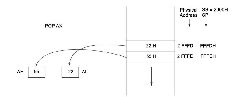
POP (Pop):
Example 1: POP AX: This instruction removes the topmost value from the stack and stores it in the AX register. For instance, if the stack contains the values [10, 20, 30] (with 30 being the topmost value), after executing POP AX, the value 30 will be stored in register AX, and the stack will become [10, 20].
Example 2: POP [SI]: Here, the instruction pops the topmost value from the stack and stores it in the memory location pointed to by the SI register.
PUSH (Push): Example 1: PUSH AX: This instruction pushes the contents of the AX register onto the stack. For instance, if AX contains the value 1234h and the stack is initially empty, executing PUSH AX will result in the stack containing [1234h].
Example 2: PUSH 5678h: In this case, the immediate value 5678h is pushed onto the stack. If the stack is initially empty, executing PUSH 5678h will result in the stack containing [5678h].
LEA (Load Effective Address):
LEA AX, [BX+2]: Loads the effective address of the memory location [BX+2] into register AX, without accessing memory. This instruction is often used for performing arithmetic operations on addresses.
LAHF (Load AH from Flags) and SAHF (Store AH into Flags):
LAHF: Loads the lower byte of the flag register (AH) into the AH register.
SAHF: Stores the lower byte of the AH register into the flag register.
XLAT (Translate):
XLAT: Translates a byte at the address formed by adding the contents of the AL register and the DS register to the contents of the DS:BX register pair, storing the result back into the AL register. This instruction is commonly used for table lookups or character conversions.
XCHG (Exchange) (Extended usage):
XCHG AX, [BX]: Exchanges the contents of register AX with the memory location pointed to by register BX.
These instructions are essential building blocks for programming tasks and are used extensively in various applications, including data processing, device control, and system communication.
Arithmetic Instructions
Arithmetic Instructions are essential for mathematical computations in computer programming. Here are some examples of arithmetic instructions:
- ADD (Addition):
- Example:
ADD AX, BXadds the value of register BX to register AX.
- SUB (Subtraction):
- Example:
SUB CX, DXsubtracts the value of register DX from register CX.
- MUL (Multiplication):
- Example:
MUL BXmultiplies the value of register BX by the value in the AX register, storing the result in AX.
- IMUL (Signed Multiplication):
- Example:
IMUL CX, SImultiplies the signed value of register SI by the value in the CX register, storing the result in CX.
- DIV (Division):
- Example:
DIV BXdivides the value in the DX:AX register pair by the value in register BX, storing the quotient in AX and the remainder in DX.
- IDIV (Signed Division):
- Example:
IDIV CXdivides the signed value in the DX:AX register pair by the value in register CX, storing the quotient in AX and the remainder in DX.
- INC (Increment):
- Example:
INC SIincrements the value in register SI by one.
- DEC (Decrement):
- Example:
DEC BXdecrements the value in register BX by one.
These examples demonstrate how arithmetic instructions are used to perform mathematical operations on data stored in registers, facilitating various computational tasks within a program.
Logical Instructions
Logical Instructions are essential for performing logical operations on data within a computer program. These instructions manipulate individual bits or groups of bits to perform tasks such as bitwise AND, bitwise OR, bitwise XOR, and logical shifts. They are commonly used for data manipulation, bitwise operations, and controlling program flow based on logical conditions.
AND: Logical AND
The AND instruction performs a bitwise AND operation between the source operand and the destination operand. The source operand can be an immediate value, a register, or a memory location, while the destination operand can be a register or a memory location. The result of the bitwise AND operation is stored in the destination operand.
It’s important to note that at least one of the operands must be a register or a memory location. Both operands cannot be memory locations or immediate values. Additionally, an immediate value cannot be used as the destination operand.
Examples of using the AND instruction:
AND AX, BX: Performs a bitwise AND operation between the values in registers AX and BX, storing the result in register AX.AND [SI], DL: Bitwise ANDs the value in register DL with the contents of the memory location pointed to by the SI register, storing the result back into the same memory location.AND CX, 0100b: Performs a bitwise AND operation between the value in register CX and the immediate binary value 0100, storing the result in register CX.
The AND instruction is commonly used for bitwise operations, masking, and clearing specific bits in data registers or memory locations.
OR: Logical OR
The OR instruction performs a bitwise OR operation between the source operand and the destination operand, similar to the AND operation. Both operands can be registers or memory locations, and the result is stored in the destination operand.
Similar to the AND operation, at least one of the operands must be a register or a memory location. Both operands cannot be memory locations, and an immediate value cannot be used as the destination operand.
Examples of using the OR instruction:
OR AX, BX: Performs a bitwise OR operation between the values in registers AX and BX, storing the result in register AX.OR [SI], DL: Bitwise ORs the value in register DL with the contents of the memory location pointed to by the SI register, storing the result back into the same memory location.OR CX, 0100b: Performs a bitwise OR operation between the value in register CX and the immediate binary value 0100, storing the result in register CX.
The OR instruction is commonly used for setting specific bits, combining flags or control bits, and performing logical operations on data within a program.
NOT: Logical Invert
The NOT instruction, also known as logical inversion, complements the contents of an operand register or a memory location bit by bit. It effectively flips each bit, changing 0s to 1s and 1s to 0s.
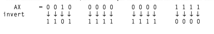
Examples of using the NOT instruction:
NOT AX: Inverts the contents of register AX, flipping each bit.NOT [SI]: Inverts the contents of the memory location pointed to by the SI register, flipping each bit in the data stored at that location.
The NOT instruction is useful for toggling individual bits or inverting data values stored in registers or memory locations. It is commonly used in bitwise operations and data manipulation tasks within a program.
XOR: Logical Exclusive OR
The XOR (Exclusive OR) operation is performed similarly to the AND and OR operations. Like those operations, XOR operates on two operands, the source and destination, and produces a result based on their bitwise comparison.
XOR gives a high output (1) when the two input bits are dissimilar (one is 1 and the other is 0). Otherwise, the output is zero (0).
Examples of using the XOR instruction:
XOR AX, BX: Performs a bitwise XOR operation between the values in registers AX and BX, storing the result in register AX.XOR [SI], DL: Bitwise XORs the value in register DL with the contents of the memory location pointed to by the SI register, storing the result back into the same memory location.XOR CX, 0100b: Performs a bitwise XOR operation between the value in register CX and the immediate binary value 0100, storing the result in register CX.
The XOR operation is commonly used for toggling bits, flipping specific bits, and performing data encryption or masking operations within a program.
TEST: Logical Compare Instruction
The TEST instruction performs a bitwise logical AND operation between two operands. It compares each bit of the operands, setting the result bit to 1 only if both corresponding bits are 1; otherwise, the result bit is set to 0.
Unlike other logical operations, the result of the TEST operation is not stored for further use. Instead, the TEST instruction is primarily used for comparing values and setting flags based on the comparison result. The flags affected by the TEST instruction include OF (Overflow Flag), CF (Carry Flag), SF (Sign Flag), ZF (Zero Flag), and PF (Parity Flag).
The operands for the TEST instruction can be registers, memory locations, or immediate data values.
Examples of using the TEST instruction:
TEST AX, BX: Performs a bitwise AND operation between the values in registers AX and BX, setting the flags based on the comparison result.TEST [SI], DL: Compares the value in register DL with the contents of the memory location pointed to by the SI register, setting the flags accordingly.TEST CX, 0100b: Compares the value in register CX with the immediate binary value 0100, setting the flags based on the comparison result.
The TEST instruction is commonly used for conditional branching and bitwise testing within a program, allowing for efficient comparison of values and setting of flags for subsequent instructions.
SHL/SAL: Shift Logical/Arithmetic Left
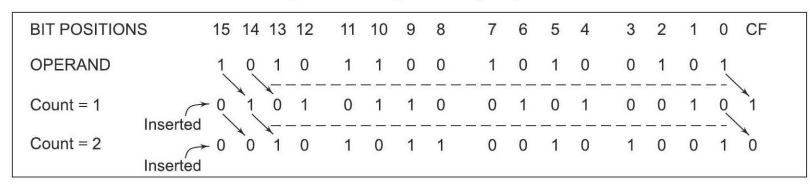
The SHL (Shift Logical Left) and SAL (Shift Arithmetic Left) instructions shift the bits of the operand, whether it’s a word or a byte, to the left by one position or by the count specified in the CL register. During the shift, zeros are inserted into the newly introduced least significant bits.
In all SHIFT and ROTATE instructions, including SHL/SAL, the shift count can be either 1 or specified by the contents of the CL register. The operand can be located in a register or a memory location, but it cannot be an immediate data value.
These instructions affect all flags depending on the result of the shift operation. Additionally, it’s important to note that the shift operation utilizes the carry flag.
The below Figure illustrates the execution of the SHL/SAL instruction, providing a visual representation of how the shift operation modifies the operand.
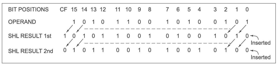
The SHL/SAL instructions are commonly used for bitwise manipulation, data encryption, and arithmetic operations in computer programming, providing flexibility in shifting and modifying data within a program.
SHR: Shift Logical Right
The SHR (Shift Logical Right) instruction performs bitwise right shifts on the operand, whether it’s a word or a byte. This means each bit of the operand is shifted to the right by the specified count in the instruction, and zeros are inserted into the shifted positions. The result is then stored in the destination operand, which can be a register or a memory location.
Similar to other shift instructions, the count for the shift operation in SHR can be specified directly in the instruction or by the contents of the CL register. The operand itself cannot be an immediate data value; it must be located in a register or a memory location.
During the shift operation, all flags may be affected depending on the result. Additionally, the shift operation in SHR is carried out through the carry flag.
The below Figure provides an illustration explaining the execution of the SHR instruction, giving a visual representation of how the right shift operation modifies the operand.
The SHR instruction is commonly used in bitwise manipulation, data encryption, and arithmetic operations in computer programming to efficiently shift and modify data within a program.
SHR: Shift Logical Right
The SHR (Shift Logical Right) instruction executes bitwise right shifts on the operand, which can be a word or a byte stored in a register or a memory location. It shifts each bit of the operand to the right by the specified count indicated in the instruction. As a result, zeros are inserted into the vacated positions after the shift. The outcome of the shift operation is then stored in the destination operand.
In the SHR instruction, the count for the shift operation is determined by the value specified in the instruction itself or by the content of the CL register. However, the operand cannot be an immediate data value; it must be located in either a register or a memory location.
During the shift operation, all flags may be influenced based on the outcome. It’s noteworthy that the SHR instruction executes the shift operation utilizing the carry flag.
The SHR instruction is frequently utilized in various programming scenarios, including bitwise operations, data encryption, and arithmetic calculations, enabling efficient manipulation and modification of data within software applications.
SAR: Shift Arithmetic Right
The SAR (Shift Arithmetic Right) instruction performs right shifts on the operand, which can be a word or a byte stored in a register or a memory location. It shifts each bit of the operand to the right by the specified count indicated in the instruction, while preserving the sign bit by inserting the most significant bit of the operand in the vacated positions. The result of the shift operation is then stored in the destination operand.
During the execution of the SAR instruction, all condition code flags may be affected. It’s important to note that this shift operation also shifts the operand through the carry flag.
ROR: Rotate Right without Carry
The ROR (Rotate Right without Carry) instruction rotates the contents of the destination operand to the right (bit-wise) either by one position or by the count specified in the CL register, excluding the carry flag. Each rotation involves pushing the least significant bit into the carry flag while transferring the carry flag’s value into the most significant bit position. The remaining bits are then shifted right by the specified positions.
The ROR instruction does not affect the PF, SF, and ZF flags. The operand for this instruction can be a register or a memory location, but it cannot be an immediate operand. Figure 2.10 provides a visual explanation of how the ROR instruction operates.
ROL: Rotate Left without Carry
The ROL (Rotate Left without Carry) instruction rotates the content of the destination operand to the left by the specified count (bit-wise), excluding the carry flag. During each rotation, the most significant bit is pushed into the carry flag, and the least significant bit is pushed into the least significant bit position. The remaining bits are then shifted left by the specified count positions.
Similar to ROR, the ROL instruction does not affect the PF, SF, and ZF flags. The operand can be a register or a memory location.
RCR: Rotate Right through Carry
The RCR (Rotate Right through Carry) instruction rotates the contents of the destination operand right by the specified count through the carry flag (CF). For each operation, the carry flag is pushed into the most significant bit (MSB) of the operand, while the least significant bit (LSB) is pushed into the carry flag. The remaining bits are shifted right by the specified count positions.
The RCR instruction does not affect the SF, PF, and ZF flags. The operand may be a register or a memory location.
RCL: Rotate Left through Carry
The RCL (Rotate Left through Carry) instruction rotates the contents of the destination operand left by the specified count through the carry flag (CF). In each operation, the carry flag is pushed into the least significant bit (LSB) of the operand, while the most significant bit (MSB) of the operand is pushed into the carry flag. The remaining bits are then shifted left by the specified positions.
Similar to RCR, the RCL instruction does not affect the SF, PF, and ZF flags. The operand can be a register or a memory location.
String Manipulation Instructions
A sequence of data bytes or words stored in consecutive memory locations, collectively referred to as byte strings or word strings, are essential in many computing tasks. For instance, a string of characters might occupy consecutive memory locations, with each character represented by its ASCII code.
To reference a string, two pieces of information are necessary:
(a) the starting or ending address of the string, and
(b) the length of the string.
In the context of 8085, similar structures can be established using pointer and counter arrangements. These arrangements are typically modified at each iteration until the required condition for proceeding further is met.
However, the 8086 architecture provides a more robust set of instructions for string manipulation. In these instructions, the incrementing or decrementing of the pointer depends on the status of the Direction Flag (DF).
- For byte string operations, the index registers are updated by one, and
- for word string operations, they are updated by two.
Regardless of the string type, the counter is decremented by one after each operation. This approach allows for efficient manipulation and processing of strings within the memory.
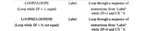
REP: Repeat Instruction Prefix
The REP instruction prefix is utilized to repeat other instructions until the CX register reaches zero, with CX automatically decremented by one at each iteration. Once CX becomes zero, the execution proceeds to the next instruction in sequence. Two additional options of the REP instruction exist:
- REPE/REPZ: Repeats the operation while equal/zero.
- REPNE/REPNZ: Repeats the operation while not equal/not zero.
These options are specifically employed with CMPS and SCAS instructions as instruction prefixes.
MOVSB/MOVSW: Move String Byte or String Word
When moving a string of bytes or words from one memory location to another, the MOVSB/MOVSW instructions are used. These instructions move a string of bytes or words pointed to by the DS:SI pair (source) to the memory location indicated by the ES:DI pair (destination). The REP instruction prefix is used with MOVS instructions to repeat them based on the value stored in the counter register CX, which must hold the length of the byte or word string. No flags are affected by this instruction.
After executing the MOVS instruction once, the index registers are automatically updated, and CX is decremented. The updating of the pointers, SI and DI, depends on the direction flag DF. If DF is 0, the index registers are incremented; otherwise, they are decremented for all string manipulation instructions.
CMPS: Compare String Byte or String Word
CMPS instruction compares two strings of bytes or words. The length of the string is stored in the CX register. If both strings are equal, the zero flag is set. The flags are affected in the same manner as the CMP instruction. The REP instruction prefix repeats the operation until CX becomes zero or the condition specified by the REP prefix is false.
SCAS: Scan String Byte or String Word
The SCAS instruction scans a string of bytes or words for an operand byte or word specified in the AL or AX register. The string is pointed to by the ES:DI register pair, and the length of the string is stored in CX. The direction flag DF controls the scanning mode, similar to the MOVSB instruction. If a match to the specified operand is found in the string, the execution stops, and the zero flag is set. Otherwise, the zero flag is reset. The REPNE prefix is used with the SCAS instruction to repeat the operation until a match is found.
LODS: Load String Byte or String Word
LODS instruction loads the AL/AX register with the content of a string pointed to by the DS:SI register pair. The SI is modified automatically depending on the DF. If it is a byte transfer (LODSB), SI is modified by one; if it is a word transfer (LODSW), SI is modified by two. No other flags are affected by this instruction.
STOS: Store String Byte or String Word
STOS instruction stores the contents of the AL/AX register to a location in the string pointed by the ES:DI register pair. DI is modified accordingly. No flags are affected by this instruction.
The direction flag controls the execution of string instructions. SI and DI are automatically modified after each iteration, depending on whether DF is set to 0 or 1, following autoincrement or autodecrement mode, respectively. In autodecrement mode, the strings are referred to by their ending addresses, while in autoincrement mode, they are referred to by their starting addresses.
Control Transfer or Branching Instructions
Control transfer instructions alter the flow of program execution by directing it to a new address specified within the instruction. When executed, these instructions load the CS (Code Segment) and IP (Instruction Pointer) registers with new values corresponding to the location where execution will continue. Control transfer instructions are categorized into two types:
- Unconditional Control Transfer (Branch) Instructions: These instructions transfer execution control to a specified location without considering any status or condition. Both CS and IP are unconditionally modified to new values.
- Conditional Control Transfer (Branch) Instructions: In conditional control transfer instructions, execution control shifts to a specified location only if the result of the previous operation satisfies a specific condition. Otherwise, the program continues executing in its normal sequence. The condition is typically determined by the state of condition code flags, which reflect the results of previous operations. With these instructions, control is transferred to a specified location based on whether a particular flag meets the condition.
Unconditional Branch Instructions
Unconditional Call (CALL):
The CALL instruction is utilized to invoke a subroutine from the main program. In assembly language programming, the term “procedure” is often used interchangeably with “subroutine”. The address of the procedure can be specified directly or indirectly, depending on the addressing mode. There are two types of procedures: those available within the same segment (Near CALL, with a displacement of +32K) and those in another segment (FAR CALL, which can be anywhere outside the segment). These are referred to as intrasegment and intersegment addressing modes, respectively.
Upon execution, this instruction stores the incremented Instruction Pointer (IP), which denotes the address of the next instruction, and Code Segment (CS) onto the stack. It then loads the CS and IP registers with the segment and offset addresses of the procedure to be called. In the case of a Near CALL, only the IP register is pushed onto the stack, while in a FAR CALL, both IP and CS are pushed onto the stack. The distinction between NEAR and FAR CALLS is made using opcodes.
Return (RET):
At each CALL instruction, the IP and CS of the next instruction are pushed onto the stack before control is transferred to the procedure. Upon reaching the end of the procedure, the RET instruction must be executed. This retrieves the previously stored content of IP and CS, along with flags, from the stack, and the execution of the main program resumes. The procedure may be either near or far. In the case of a FAR procedure, the current contents of the Stack Pointer (SP) point to IP and CS at the time of return, while in the case of a NEAR procedure, it points only to IP. Depending on the type of procedure and the SP contents, the RET instruction can be of four types: Return within segment, Return within segment adding 16-bit immediate displacement to the SP contents, Return intersegment, and Return intersegment adding 16-bit immediate displacement to the SP contents.
Interrupt Type N (INT N):
In the interrupt structure of 8086/8088, 256 interrupts are defined from 00H to FFH. When an INT N instruction is executed, the TYPE byte N is multiplied by 4, and the contents of IP and CS of the interrupt service routine are retrieved from the resultant offset address (N’4) and 0000 segment address. In other words, the multiplication of type N by 4 (offset) points to a memory block in the 0000 segment containing the IP and CS values of the interrupt service routine. For the execution of this instruction, the Interrupt Flag (IF) must be enabled.
Unconditional Jump (JMP):
The JMP instruction unconditionally transfers control of execution to the specified address using an 8-bit or 16-bit displacement (intrasegment relative, short or long) or CS: IP (intersegment direct far). This instruction does not affect any flags.
Return from Interrupt Service Routine (IRET):
Before transferring control to an interrupt service routine (ISR), the IP, CS, and flag register are stored onto the stack to indicate the location from where the execution is to be continued after the ISR is executed. When IRET is executed at the end of each ISR, the values of IP, CS, and flags are retrieved from the stack to continue the execution of the main program. The stack is modified accordingly.
Loop Unconditionally (LOOP):
The LOOP instruction executes the part of the program from the label or address specified in the instruction up to the loop instruction a specified number of times (CX). At each iteration, CX is decremented automatically, implementing a “decrement counter and jump if not zero” structure. After the loop is executed, execution proceeds sequentially for CX number of times. If CX is already 00H, execution continues sequentially. This instruction does not affect any flags.
Conditional Branch Instructions
When these instructions are executed, control of execution is shifted to the address specified relatively in the instruction, provided that the condition implicit in the opcode is met. If not, execution continues sequentially. Here, the conditions refer to the status of condition code flags. These instructions do not affect any flags. The address must be specified in the instruction relatively in terms of displacement, which must fall within the range of -80H to 7FH (or -128 to 127) bytes from the address of the branch instruction. In simpler terms, only short jumps can be made using conditional branch instructions. A label may represent the displacement if it falls within the specified range. The different 8086/8088 conditional branch instructions and their operations are listed in Table 1.
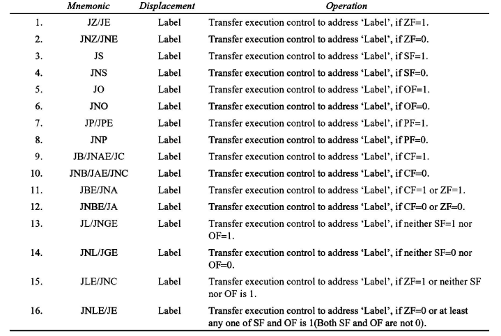
While the majority of instructions can be utilized for unsigned binary operations, the final four instructions are specifically designed for decisions based on signed binary number operations. In the context of unsigned numbers, terms like “above” and “below” are commonly used, whereas “less” and “greater” are employed for signed numbers. An example of a conditional jump instruction that doesn’t check status flags for condition testing is provided below:
JCXZ ‘Label’: Transfers execution control to the address specified by ‘Label’ if CX equals zero.
Conditional LOOP instructions, along with their meanings, are detailed in Table 2.4. These instructions find utility in implementing structures such as DO_WHILE and REPEAT_UNTIL.
Understanding these instructions thoroughly often requires practical programming experience. This section aims to introduce them to readers, with examples provided where possible. However, detailed explanations of JUMP and LOOP instructions will be emphasized further in Chapter 3.
Flag Manipulation and Processor Control Instructions:
These instructions govern the operation of the hardware within the processor chip and are divided into two categories: flag manipulation instructions and machine control instructions.
Flag Manipulation Instructions directly modify certain flags of the 8086 processor. They include:
- CLC: Clear carry flag
- CMC: Complement carry flag
- STC: Set carry flag
- CLD: Clear direction flag
- STD: Set direction flag
- CLI: Clear interrupt flag
- STI: Set interrupt flag
These instructions alter the Carry (CF), Direction (DF), and Interrupt (IF) flags directly. The DF and IF flags, modified by these instructions, further influence processor operation, such as interrupt responses and auto-increment or auto-decrement modes. Consequently, these instructions may also be referred to as machine or processor control instructions. Flags other than CF can be modified using POPF and SAHF instructions, termed as data transfer instructions in this context. No direct instructions are available for modifying status flags except the carry flag.
Machine Control Instructions supported by the 8086 and 8088 processors, listed in Table 2, perform specific functions without requiring operands. They include:
- WAIT: Waits for Test input pin to go low
- HLT: Halts the processor
- NOP: No operation
- ESC: Escape to an external device like NDP (numeric co-processor)
Flag Manipulation and Processor Control Instructions
These instructions regulate the operation of the hardware components within the processor chip. They are typically classified into two categories: flag manipulation instructions and machine control instructions.
Flag manipulation instructions directly alter specific flags of the 8086 processor, influencing its behavior. These instructions are crucial for controlling operations like interrupt responses and modes of auto-increment or auto-decrement. The flags primarily affected are the Carry (CF), Direction (DF), and Interrupt (IF) flags. Modifying the DF and IF flags using these instructions can further control processor behavior. Instructions such as POPF and SAHF, termed as data transfer instructions, can manipulate other flags besides the carry flag. However, no direct instructions are available for modifying status flags other than the carry flag.
Machine control instructions, listed in Table 3, govern bus usage and execution within the processor. Unlike flag manipulation instructions, machine control instructions do not require operands. They include:
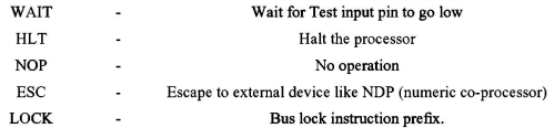
- WAIT: This instruction halts processor operation until the logic level on the TEST pin drops low. During this time, the processor inserts WAIT states in the instruction cycle.
- HLT: When executed, this instruction puts the processor into a halt state until it is reset or interrupted.
- NOP: This instruction causes the processor to perform no operation for four clock cycles, except for incrementing the Instruction Pointer (IP) by one.
- ESC: When executed, this instruction releases the bus for an external master such as a coprocessor or peripheral devices.
- LOCK prefix: When used with another instruction, the LOCK prefix prevents bus access for other masters until the prefixed instruction completes execution. This is particularly useful in programming for multiprocessor systems.
These instructions play critical roles in managing processor behavior and coordinating interactions with external devices.
ASSEMBLER DIRECTIVES AND OPERATORS
Machine language programming offers the primary advantage of direct memory control, empowering programmers to efficiently manage system memory. However, it comes with several drawbacks. Programming, coding, and resource management in machine language are cumbersome tasks, increasing the likelihood of human errors. Comprehensive technical knowledge of processor architecture and instruction sets is essential to comprehend programs effectively.
Assembly language programming, in contrast, is simpler compared to machine language. Instruction mnemonics are directly incorporated into assembly language programs, enhancing program readability. Assembly language further benefits from the use of labels to identify address values and constants. Clear labels make programs more understandable and eliminate the need for programmers to memorize various constants and addresses throughout the program. This feature streamlines byte handling and manipulation tasks.
Additionally, assembly language allows the assignment of labels to logical segments and routines instead of different addresses, maintaining memory control features while enhancing readability. Unlike machine language programming, assembly language also supports documentation, providing readers with insights into its various features.
An assembler is a crucial tool used to convert assembly language programs into equivalent machine code modules, which can then be transformed into executable codes. It determines the address of each label and substitutes values for constants and variables, ultimately forming machine code for mnemonics and data. While assemblers can identify syntax errors, they cannot detect logical or other programming errors. Assemblers rely on predefined alphabetical strings called assembler directives to correctly interpret assembly language programs and generate codes.
Operators are another type of hint that assists assemblers in assigning constants to labels or initializing memory locations with constants. Unlike directives, operators perform arithmetic and logical tasks. Commonly used directives and operators in assembly language programming, such as those utilized with Microsoft Macro Assembler or Turbo Assembler, are discussed here.
DB: Define Byte – The DB directive reserves memory locations for bytes in the available memory. During the creation of the EXE file, this directive instructs the assembler to allocate a specified number of memory bytes for the indicated data type, which could be a constant, variable, or string. Additionally, this directive can initialize the reserved memory bytes with ASCII codes of specified characters, as demonstrated in the following examples:
RANKS DB 01H, 02H, 03H, 04H
MESSAGE DB 'GOOD MORNING'
VALUE DB 50H
In these examples, the DB directive reserves memory locations and initializes them with specified values or characters.
DW: Define Word – Similar to the DB directive, the DW directive reserves memory but for 16-bit words instead of bytes. The lower bytes are stored at lower memory addresses, while the upper bytes are stored at higher addresses. Examples include:
WORDS DW 1234H, 4567H, 78ABH, 045CH
WDATA DW 5 DUP (6666H)
In the second example, the DUP operator initializes multiple memory locations with the specified word value.
DQ: Define Quadword – This directive reserves memory for 8-byte (quadword) variables and may initialize them with specified values.
DT: Define Ten Bytes – The DT directive defines variables requiring 10 bytes for storage and initializes them with specified values. It’s typically used for variables undergoing heavy numerical calculations.
ASSUME: Assume Logical Segment Name – The ASSUME directive informs the assembler about the logical segment names used in the program. Each segment, such as code or data, is given a name, and ASSUME directs the assembler to associate these names with the appropriate segment addresses during program execution.
END: End of Program – Marks the end of an assembly language program. When encountered, the assembler ignores subsequent source lines, so it should be the final statement in the file.
ENDP: End of Procedure – Indicates the end of a procedure or subroutine. Statements following ENDP within the same module are disregarded as part of that procedure.
ENDS: End of Segment – Marks the end of a logical segment in the program. All segment contents should appear between the SEGMENT and ENDS statements.
EVEN: Align on Even Memory Address – This directive ensures that subsequent instructions or variables are aligned to even memory addresses. If the current address is odd, the location counter is updated to the next even address.
EQU: Equate – Assigns a label with a specific value or symbol, reducing the repetition of numerical values or constants in the program. Labels defined with EQU can be used in place of the corresponding values throughout the program.
EXTRN: External and PUBLIC: Public – Informs the assembler about external names, procedures, or labels defined in other modules, allowing cross-module referencing. EXTRN is accompanied by PUBLIC declarations in the source module where these names are defined.
GROUP: Group the Related Segments – Forms logical groups of segments with similar purposes or types, ensuring they reside within the same memory segment. This facilitates addressing using a single segment base for all grouped segments.
LABEL: Label – The Label directive assigns a name to the current content of the location counter during the assembly process. As assembly begins, the assembler initializes a location counter to track memory locations assigned to the program. As assembly proceeds, the location counter is updated accordingly. When the assembler encounters the LABEL directive, it assigns the specified label with the current contents of the location counter. It’s important to specify the type of label, such as whether it’s NEAR or FAR, BYTE or WORD, etc.
The LABEL directive can be used to facilitate FAR jumps. For example, to enable a FAR jump, the label CONTINUE can be designated as a FAR label:
CONTINUE LABEL FAR
This designation allows for a FAR jump, which cannot typically be executed at a normal label with a colon. By using the LABEL directive, programmers can effectively manage program flow and memory addressing within the assembly language code.
LENGTH: Byte Length of a Label – This directive, not available in MASM, refers to the length of a data array or a string. For instance, the statement MOV CX, LENGTH ARRAY will, upon assembly, substitute the length of the array ARRAY in bytes into the instruction.
LOCAL – Labels, variables, constants, or procedures declared as LOCAL in a module are meant to be used exclusively within that module. Another module may later declare the same identifier as LOCAL for a different purpose. With a single declaration statement, multiple variables can be declared local.
NAME: Logical Name of a Module – The NAME directive assigns a name to an assembly language program module, aiding in documentation and understanding. Selecting suggestive names for modules can clarify their functions.
OFFSET: Offset of a Label – When encountered with a label, the OFFSET operator computes the 16-bit displacement (offset) of that label and substitutes the ‘OFFSET LABEL’ string with the computed displacement. This operator is commonly used to determine the offset of arrays, strings, labels, and procedures within their default segments.
ORG: Origin – The ORG directive instructs the assembler to start memory allocation for a specific segment, block, or code from the declared address. It enables programmers to dictate where code or data should begin in memory.
PROC: Procedure – The PROC directive marks the beginning of a named procedure, specifying whether it’s NEAR or FAR. NEAR procedures are called by programs within the same segment of memory, while FAR procedures can be called from different segments.
PTR: Pointer – The PTR operator declares the type of a label, variable, or memory operand as either BYTE or WORD, specifying whether it’s treated as an 8-bit or 16-bit quantity, respectively. It’s commonly used in memory addressing and data manipulation instructions.
PUBLIC – Labels, variables, constants, or procedures declared PUBLIC can be accessed by other modules within the program. This directive, along with EXTRN, facilitates inter-module communication and sharing of resources.
SEG: Segment of a Label – The SEG operator determines the segment address of a label, variable, or procedure, substituting the segment base address in place of ‘SEG’ label. It’s used to facilitate memory addressing, especially in indirect or indexed addressing modes.
SEGMENT: Logical Segment – The SEGMENT directive marks the beginning of a logical segment and assigns it a name (label). SEGMENT and ENDS directives must enclose each logical segment of a program, facilitating organization and memory management.
SHORT – The SHORT operator indicates to the assembler that only one byte is needed to code the displacement for a jump. This optimization saves memory by using shorter jump addresses when possible.
TYPE – The TYPE operator instructs the assembler to determine the data type of a specified label and replaces the ‘TYPE’ label with the corresponding data type value. It’s useful for identifying the size of variables or data structures.
GLOBAL – Labels, variables, constants, or procedures declared GLOBAL are accessible by other modules within the program, promoting modularity and code reuse.
“+ & -” Operators – These operators perform arithmetic addition and subtraction, commonly used for manipulating memory addresses or pointers in assembly language instructions.
FAR PTR and NEAR PTR – These directives specify the addressing mode for labels, indicating whether they require a 32-bit (FAR PTR) or 16-bit (NEAR PTR) address. They are used in instructions involving jumps or calls to different segments of memory. If a label is not prefixed by NEAR PTR or FAR PTR, it’s considered a NEAR PTR label by default.
Dos and Don’ts While Using Instructions
Dos:
1) Visualize Clearly: Clearly visualize the logic required for implementing a program, opting for the simplest method.
2) Express with Flowcharts: Express the selected logic using flowcharts or algorithms.
3) Select Appropriate Instructions: Identify the most suitable instructions to implement the algorithmic steps.
4) Arrange Logically: Arrange instructions in a logical sequence to effectively solve the problem.
5) Use Efficient Instructions: Opt for more efficient instructions in terms of byte length and execution time, such as using INC AL instead of ADD AL, 01H.
6) Simulate on Paper: Simulate the program on paper with various input scenarios to validate its functionality.
7) Provide Comments: Include comments with each instruction explaining its role in the overall implementation.
8) Remove Redundancy: Remove unnecessary or redundant instructions from the program to streamline it.
9) Iterate if Necessary: If simulation reveals errors, go back to step 3 and iterate the process.
Don’ts:
1) Unclear Operations: Avoid using instructions until you fully understand their operation and role in the logic implementation.
2) Complex Addressing Modes: Avoid unnecessarily complex addressing modes and instructions unless simpler alternatives are unavailable. Use indirect addressing modes conservatively.
3) Mismatching Operand Sizes: Avoid using operands of mismatching sizes in instructions unless explicitly required by the operation.
4) Multiple Memory Operands: Do not use both operands in an instruction as memory operands. Only one memory operand is allowed per instruction.
5) Immediate Destination Operands: Do not use immediate 8-bit or 16-bit operands as destination operands. Destination operands must be storage elements like registers or memory locations.
6) Both Operands Immediate: Avoid using immediate operands for both operands of an instruction.
7) Avoid Unnecessary Stack Operations: Use stack operations judiciously and only when necessary.
8) Avoid Monolithic Programs: Refrain from writing excessively large, continuous single programs for an application. Instead, divide tasks into smaller modules and write modular programs using subroutines or interrupt service routines if needed.
9) Avoid Using Segment Registers as Operands: Do not use segment registers as operands for arithmetic or logical instructions; it is not permitted.