Two-dimensional (2D) viewing in computer graphics refers to the process of displaying and manipulating objects or scenes in a two-dimensional space. It involves transforming and projecting objects onto a two-dimensional plane, typically a computer screen, to create the illusion of depth and perspective.
In 2D viewing, the objects are represented using coordinates in a Cartesian coordinate system, with an x-axis and a y-axis. The viewing process involves several steps:
- Object Representation: Objects or shapes are defined by their geometric properties, such as vertices, edges, and surfaces. These properties are typically stored as mathematical equations or data structures.
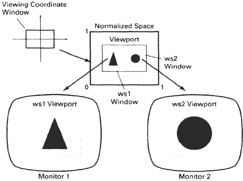
- Viewport and Window: The viewport represents the actual display area on the screen where the objects will be rendered. It is usually defined by its dimensions and position on the screen. The window represents the region of the entire scene that will be visible within the viewport.
- Viewing Transformation: The viewing transformation maps the objects from their world coordinates to the normalized device coordinates (NDC). It involves translation, rotation, and scaling operations to align the objects with the viewport and window.
- Clipping: Clipping is the process of removing any objects or parts of objects that fall outside the defined window boundaries. This ensures that only the visible portion of the scene is displayed.
- Projection: Projection transforms the 3D objects into 2D space. The most common projection techniques used in 2D viewing are orthographic and perspective projections. Orthographic projection preserves the relative size and shape of objects, while perspective projection creates the illusion of depth and distance by simulating the way objects appear in the real world.
- Rasterization: Rasterization converts the mathematical representation of objects into pixel-based images. It involves determining which pixels on the screen are covered by the objects and assigning appropriate color values to those pixels.
- Display: Finally, the pixel values obtained from rasterization are sent to the display device, which generates the visual output on the screen.
THE VIEWING PIPELINE
The viewing pipeline, also known as the graphics pipeline or rendering pipeline, is a sequence of stages that transform and process geometry and textures to generate a final image on the screen. It is a fundamental concept in computer graphics and is used to render both two-dimensional (2D) and three-dimensional (3D) scenes. Here is an overview of the stages involved in the typical viewing pipeline:
- Application Stage: In this stage, the application software provides the 3D scene data, including geometry, materials, and textures. The application stage also includes high-level operations such as scene setup, animation, and interaction.
- Geometry Stage: The geometry stage processes the 3D geometric data, including vertices, edges, and polygons. It performs transformations like translation, rotation, and scaling to position and orient the objects in the scene correctly. Clipping is also performed in this stage to remove any geometry that lies outside the view frustum, which is the portion of the scene that is visible from the camera’s perspective.
- Rasterization Stage: Rasterization converts the transformed geometric primitives into pixels on the screen. It determines which pixels are covered by the polygons and generates fragments (potential pixels) for further processing. Each fragment carries information such as position, color, texture coordinates, and depth.
- Fragment Stage: The fragment stage processes individual fragments generated by rasterization. It performs operations like depth testing to determine the visible fragments and discard hidden or occluded fragments. Other operations include shading, which calculates the final color of each fragment based on lighting models and material properties. Texturing is also applied at this stage to map appropriate textures onto the fragments.
- Display Stage: Finally, the display stage takes the processed fragments and converts them into the final image that is displayed on the screen. It applies any necessary post-processing effects like anti-aliasing or blending, and then sends the pixel data to the display device for presentation.
The viewing pipeline is executed by dedicated hardware components in modern graphics processing units (GPUs) or programmable shaders, which can accelerate the rendering process by performing parallel computations.
By following the stages of the viewing pipeline, the computer graphics system transforms the input scene into a visually appealing and realistic image that can be observed by the viewer. The pipeline can be extended or modified to incorporate additional effects or techniques based on the specific requirements of the application.
VIEWING COORDINATE REFERENCE FRAME
The viewing coordinate reference frame, also known as the camera coordinate system or eye coordinate system, is a coordinate system used in computer graphics to represent the viewpoint or camera position in a 3D scene. It defines the position, orientation, and direction of the camera in relation to the objects in the scene. The viewing coordinate reference frame is an essential component in the rendering process to determine the perspective and view of the scene.
The viewing coordinate reference frame consists of the following components:
- Eye/Camera Position: The eye or camera position represents the location of the viewer or camera in the scene. It is defined by a 3D point (x, y, z) that specifies the position in the world coordinate system.
- Look-at Point: The look-at point is the point in the scene towards which the camera is directed. It is also defined by a 3D point (x, y, z) in the world coordinate system.
- Up Vector: The up vector defines the orientation of the camera by specifying which direction is considered “up.” It is typically a unit vector (u, v, w) and is orthogonal to the line of sight, helping to determine the rotation of the camera.
- Viewing Direction: The viewing direction is the vector pointing from the eye position to the look-at point. It is calculated as the normalized vector from the eye position to the look-at point.
With these components, the viewing coordinate reference frame can be established using the following steps:
- Calculate the viewing direction vector by subtracting the eye position from the look-at point.
- Normalize the viewing direction vector to ensure it has unit length.
- Calculate the cross product between the up vector and the viewing direction vector to obtain a vector orthogonal to both, known as the “right” vector.
- Normalize the right vector to ensure it has unit length.
- Calculate the cross product between the viewing direction vector and the right vector to obtain the true up vector.
Once the viewing coordinate reference frame is established, it can be used to transform the objects in the scene from the world coordinate system to the camera coordinate system. This transformation involves translating the objects relative to the camera position and orienting them according to the camera’s viewing direction, up vector, and right vector.
By defining and manipulating the viewing coordinate reference frame, computer graphics systems can create various perspectives and viewpoints, enabling the rendering of 3D scenes from different camera positions and orientations, and providing a realistic representation of the scene as perceived by a viewer.
WINDOW-TO-VIEWPORT COORDINATE TRANSFORMATION
The viewing coordinate reference frame, also known as the camera coordinate system or eye coordinate system, is a coordinate system used in computer graphics to represent the viewpoint or camera position in a 3D scene. It defines the position, orientation, and direction of the camera in relation to the objects in the scene. The viewing coordinate reference frame is an essential component in the rendering process to determine the perspective and view of the scene.
The viewing coordinate reference frame consists of the following components:
- Eye/Camera Position: The eye or camera position represents the location of the viewer or camera in the scene. It is defined by a 3D point (x, y, z) that specifies the position in the world coordinate system.
- Look-at Point: The look-at point is the point in the scene towards which the camera is directed. It is also defined by a 3D point (x, y, z) in the world coordinate system.
- Up Vector: The up vector defines the orientation of the camera by specifying which direction is considered “up.” It is typically a unit vector (u, v, w) and is orthogonal to the line of sight, helping to determine the rotation of the camera.
- Viewing Direction: The viewing direction is the vector pointing from the eye position to the look-at point. It is calculated as the normalized vector from the eye position to the look-at point.
With these components, the viewing coordinate reference frame can be established using the following steps:
- Calculate the viewing direction vector by subtracting the eye position from the look-at point.
- Normalize the viewing direction vector to ensure it has unit length.
- Calculate the cross product between the up vector and the viewing direction vector to obtain a vector orthogonal to both, known as the “right” vector.
- Normalize the right vector to ensure it has unit length.
- Calculate the cross product between the viewing direction vector and the right vector to obtain the true up vector.
Once the viewing coordinate reference frame is established, it can be used to transform the objects in the scene from the world coordinate system to the camera coordinate system. This transformation involves translating the objects relative to the camera position and orienting them according to the camera’s viewing direction, up vector, and right vector.
By defining and manipulating the viewing coordinate reference frame, computer graphics systems can create various perspectives and viewpoints, enabling the rendering of 3D scenes from different camera positions and orientations, and providing a realistic representation of the scene as perceived by a viewer.
TWO-DIMENSIONAL \/IEWING FUNCTIONS
In two-dimensional (2D) computer graphics, various viewing functions are used to manipulate and control the display of objects or scenes on the screen. These functions help determine the visibility, position, size, and appearance of objects within the viewing area. Here are some common 2D viewing functions:
- Clipping: Clipping is a function that removes or discards parts of objects that lie outside the viewing area, such as the viewport or window. It ensures that only the visible portions of objects are displayed, improving efficiency and reducing unnecessary computations.
- Scaling: Scaling is a function that alters the size of objects relative to a reference point or origin. It can be used to zoom in or zoom out on objects, making them appear larger or smaller on the screen. Scaling is typically achieved by multiplying the coordinates of objects by scaling factors.
- Translation: Translation is a function that moves objects in the viewing area without altering their size or shape. It is used to reposition objects on the screen by adding or subtracting specific values from their coordinates. Translation allows objects to be moved horizontally, vertically, or diagonally.
- Rotation: Rotation is a function that changes the orientation of objects around a reference point or origin. It is used to rotate objects clockwise or counterclockwise by a certain angle. Rotation is achieved through mathematical transformations that modify the coordinates of objects based on rotation formulas.
- Shearing: Shearing is a function that skews the shape of objects by displacing points along one axis relative to another axis. It is useful for creating effects like slanting or tilting objects. Shearing is typically controlled by shearing factors that determine the amount and direction of the skewing.
- Mirroring/Flipping: Mirroring or flipping is a function that reflects objects across a specified axis, resulting in a reversed or mirrored appearance. It can be applied horizontally or vertically, reversing the object’s coordinates or altering the winding order of its vertices.
- Windowing: Windowing is a function that defines a rectangular viewing area, known as the window or viewport, within the screen. It specifies the boundaries of the region where objects will be displayed. Windowing determines the portion of the scene that is visible to the viewer.
These 2D viewing functions can be combined and applied sequentially or simultaneously to achieve desired visual effects and transformations in computer graphics. They provide the means to control the positioning, size, orientation, and visibility of objects, allowing for dynamic and interactive displays of 2D scenes.
CLIPPING OPERATIONS
Clipping operations in computer graphics are used to remove or discard parts of objects or primitives that lie outside the viewing area or window. Clipping ensures that only the visible portions of objects are displayed, optimizing rendering and improving efficiency. There are several types of clipping operations commonly employed:
- Point Clipping: Point clipping involves determining whether a point lies within the defined viewing area or window. If a point is outside the window boundaries, it is discarded and not displayed. Otherwise, it is considered for further processing or rendering.
- Line Clipping: Line clipping determines the visibility and position of lines or line segments within the viewing area. If a line lies completely outside the window, it is rejected and not displayed. If a line intersects the window, it is clipped to the portion that falls within the window boundaries. Various line clipping algorithms, such as Cohen-Sutherland and Liang-Barsky, are used to efficiently perform line clipping.
- Polygon Clipping: Polygon clipping involves determining the visibility and position of polygons within the viewing area. If a polygon lies completely outside the window, it is rejected and not displayed. If a polygon intersects the window, it is clipped to the portion that falls within the window boundaries. Sutherland-Hodgman and Weiler-Atherton are common polygon clipping algorithms used to perform this operation.
- Curve Clipping: Curve clipping deals with the visibility and position of curved objects, such as Bezier curves or B-splines, within the viewing area. Similar to line and polygon clipping, if a curve lies completely outside the window, it is discarded. If a curve intersects the window, it is clipped to the portion that falls within the window boundaries. Curve clipping algorithms are typically based on recursive or subdivision approaches.
- Clipping against Other Objects: In addition to window-based clipping, objects can also be clipped against other objects in the scene. For example, a polygon may need to be clipped against other polygons to ensure correct rendering and visibility. Clipping against objects involves determining the intersection regions and modifying the objects accordingly.
Clipping operations play a crucial role in computer graphics, particularly in rendering scenes efficiently and accurately. By removing non-visible portions of objects, clipping reduces unnecessary computations and improves the overall rendering performance, leading to more realistic and visually appealing displays.
- Point Clipping:
Point clipping involves determining whether a point lies within the defined viewing area or window. The window is typically defined by its minimum and maximum coordinates, (x_min, y_min) for the lower-left corner and (x_max, y_max) for the upper-right corner. To perform point clipping, we compare the coordinates of the point with the window boundaries. If the point lies within the window, it is considered visible; otherwise, it is discarded and not displayed.
Mathematically, let’s consider a point P(x, y). To perform point clipping against a window defined by (x_min, y_min) and (x_max, y_max), the condition is:
x_min ≤ x ≤ x_max
y_min ≤ y ≤ y_max
If the point satisfies these conditions, it lies within the window and is considered visible.
- Line Clipping:
Line clipping involves determining the visibility and position of lines or line segments within the viewing area. Various algorithms, such as Cohen-Sutherland and Liang-Barsky, can be used to efficiently perform line clipping.
a. Cohen-Sutherland Line Clipping:
Cohen-Sutherland algorithm uses a region code to classify each endpoint of a line segment relative to the window boundaries. The region codes represent the relationship of a point with respect to the window. The region codes can be defined as follows:
- Left of window: 0001
- Right of window: 0010
- Below window: 0100
- Above window: 1000
Based on these region codes, we can determine if a line segment is completely outside, completely inside, or partially inside the window. The algorithm then performs line clipping by calculating the intersection points between the line and the window boundaries.
b. Liang-Barsky Line Clipping:
Liang-Barsky algorithm uses parameterization of a line segment to determine if it intersects the window boundaries. The algorithm checks for potential intersections at each window boundary by calculating the parameter values corresponding to the intersections. If there are intersections, the line segment is clipped accordingly.
- Polygon Clipping:
Polygon clipping involves determining the visibility and position of polygons within the viewing area. Algorithms such as Sutherland-Hodgman and Weiler-Atherton are commonly used for polygon clipping.
a. Sutherland-Hodgman Polygon Clipping:
Sutherland-Hodgman algorithm clips a polygon against each edge of the window. It iteratively processes each edge and computes the intersection points between the polygon and the window edges. The resulting clipped polygon is constructed from the calculated intersection points.
b. Weiler-Atherton Polygon Clipping:
Weiler-Atherton algorithm is a more complex polygon clipping algorithm that can handle polygons with holes. It involves creating intersection points between the polygon edges and the window boundaries, followed by traversing the resulting polygons to construct the final clipped polygons.
- Curve Clipping:
Curve clipping deals with the visibility and position of curved objects, such as Bezier curves or B-splines, within the viewing area. The clipping of curved objects typically involves subdividing the curves and performing clipping on the resulting segments.
Each curved object has its own mathematical representation and specific clipping algorithms designed for those representations. The exact mathematical points and algorithms used would depend on the specific type of curve being clipped.
These are the general mathematical concepts and algorithms used for each type of clipping operation. The details and specific equations may vary depending on the algorithm or technique being used for clipping.
TEXT CLIPPING
Text clipping is a process in computer graphics that involves determining the visibility and position of text within a defined viewing area or window. It ensures that only the visible portions of text are displayed, while the parts outside the window boundaries are clipped or truncated.
Text clipping is typically performed by considering the bounding box of the text, which represents the smallest rectangle that encloses the entire text string. The bounding box is defined by its minimum and maximum coordinates, usually (x_min, y_min) for the lower-left corner and (x_max, y_max) for the upper-right corner.
To perform text clipping, the coordinates of the bounding box are compared with the window boundaries. Depending on the specific requirements, there are different approaches to handle text clipping:
- Discarding Approach:
In this approach, if any part of the text’s bounding box lies outside the window boundaries, the entire text string is discarded and not displayed. This approach ensures that only fully visible text is shown, but it may result in the loss of some information. - Truncation Approach:
In the truncation approach, if any part of the text’s bounding box lies outside the window boundaries, the text string is clipped or truncated at the point where it intersects with the window edges. The portion of the text that lies outside the window is not displayed, while the visible part is rendered. This approach allows for partial visibility of the text and can be useful in situations where retaining some information is important.
The specific implementation of text clipping may vary depending on the rendering system or library being used. However, the underlying principle remains the same: comparing the bounding box coordinates of the text with the window boundaries to determine its visibility and performing clipping accordingly.
Text clipping is particularly important in user interfaces, document rendering, and graphics applications where text needs to be displayed within a constrained area. By ensuring that only visible portions of text are rendered, text clipping helps optimize space utilization and improve the overall readability and appearance of the displayed text.